
Home>Create & Decorate>DIY & Crafts>Simple Breadboard Circuits: DIY Guide For Crafting
DIY & Crafts
Simple Breadboard Circuits: DIY Guide For Crafting
Published: May 27, 2024

Senior Editor in Create & Decorate, Kathryn combines traditional craftsmanship with contemporary trends. Her background in textile design and commitment to sustainable crafts inspire both content and community.
Discover how to create simple breadboard circuits with this comprehensive DIY guide. Perfect for DIY & Crafts enthusiasts looking to craft their own electronic projects.
(Many of the links in this article redirect to a specific reviewed product. Your purchase of these products through affiliate links helps to generate commission for Twigandthistle.com, at no extra cost. Learn more)
Introduction
Are you ready to dive into the world of DIY electronics? If you're looking to start small and build your way up, then creating simple breadboard circuits is a fantastic place to begin. Whether you're a complete beginner or have some experience with electronics, this DIY guide will walk you through the basics of breadboard circuits and provide you with step-by-step instructions for crafting your own simple circuits. So, grab your tools and let's get started on this electrifying journey!
Understanding Breadboard Basics
A breadboard is a fundamental tool for prototyping and creating electronic circuits without the need for soldering. It consists of a plastic board with numerous small holes into which electronic components can be inserted. These holes are connected in specific patterns, allowing for the creation of temporary circuits. The breadboard is typically divided into two main sections, separated by a central channel. The top and bottom sections are further divided into rows and columns, with each row containing multiple connected holes. The central channel is often used for placing integrated circuits (ICs) and other larger components. Understanding how the breadboard is laid out and how the connections are made is crucial for successfully building simple circuits.
When working with a breadboard, it's essential to understand the concept of tie points. Tie points are the interconnected holes within a row. Components such as resistors, LEDs, and jumper wires can be inserted into these tie points to create electrical connections. The tie points allow for the temporary placement and connection of components, enabling experimentation and modification of circuits without the need for soldering. It's important to note that tie points within the same row are electrically connected, while tie points in different rows are not connected unless a jumper wire is used to bridge the gap.
Understanding the power rails on a breadboard is also crucial. The power rails are the long strips running alongside the breadboard, typically labeled as + (positive) and – (negative). These power rails are used to provide electrical power to the components on the breadboard. The positive and negative rails are often connected to an external power source, such as a battery or a power supply. It's important to connect the components in the circuit to the appropriate power rails to ensure proper functionality.
In summary, understanding the layout of a breadboard, the concept of tie points, and the function of power rails is essential for successfully creating simple circuits. With this foundational knowledge, you'll be well-equipped to embark on the exciting journey of crafting your own breadboard circuits.
Tools and Materials Needed
When it comes to crafting simple breadboard circuits, having the right tools and materials at your disposal is essential. Here's a comprehensive list of what you'll need to get started:
Tools:
- Breadboard: The central component of your circuit-building endeavors. Ensure you have a quality breadboard with ample tie points for accommodating your components.
- Jumper Wires: These wires are used to create electrical connections between components on the breadboard. Having a variety of lengths and colors can make circuit building more organized and visually clear.
- Wire Strippers: Essential for preparing the jumper wires and ensuring clean, stripped ends for reliable connections.
- Needle-Nose Pliers: Useful for bending component leads and handling small parts during circuit assembly.
- Soldering Iron (Optional): While not necessary for breadboard circuits, a soldering iron can come in handy for more advanced projects or for securing connections on a permanent circuit board.
Materials:
- LEDs: Light-emitting diodes (LEDs) are versatile components that can be used to add visual indicators to your circuits.
- Resistors: These are crucial for controlling the flow of current in your circuits and protecting your components.
- Switches: Whether it's a toggle switch or a push-button switch, having these on hand allows you to incorporate user-controlled functionality into your circuits.
- Buzzer: Adding a buzzer to your circuits can introduce auditory feedback, expanding the interactive possibilities of your projects.
- Light Sensor: A light-sensitive resistor or photodiode can be used to create circuits that respond to changes in ambient light levels.
By ensuring you have these tools and materials ready, you'll be well-prepared to embark on your breadboard circuit crafting journey. With everything in place, you can dive into the exciting world of DIY electronics and start bringing your circuit ideas to life.
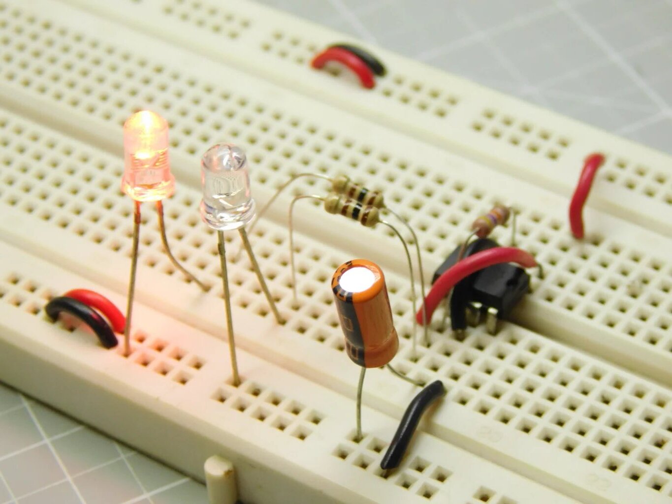
Simple LED Circuit
Creating a simple LED circuit is an excellent way to familiarize yourself with the basics of breadboard circuitry and introduce visual elements to your projects. Here's a step-by-step guide to crafting your own LED circuit:
Step 1: Gather Your Components
- LED: Select the color and size of the LED you want to use in your circuit.
- Resistor: Choose a resistor with an appropriate resistance value to limit the current flowing through the LED.
- Jumper Wires: Ensure you have jumper wires of suitable lengths to make the necessary connections on the breadboard.
Step 2: Set Up Your Breadboard
- Place the LED on the breadboard, ensuring that the longer lead (the anode) is inserted into a tie point in the positive (+) rail, and the shorter lead (the cathode) is inserted into a tie point in the main breadboard area.
- Insert the resistor into the breadboard, connecting one end to the same row as the LED's cathode and the other end to a tie point in the negative (-) rail.
Step 3: Make the Connections
- Use a jumper wire to connect the positive (+) rail to the positive terminal of your power source (e.g., a battery or power supply).
- Connect the negative (-) rail to the negative terminal of your power source.
- Ensure that the components are securely connected and that there are no loose connections or short circuits.
Step 4: Power Up Your Circuit
Once your LED circuit is assembled, apply power to the breadboard by connecting the power source. If everything is connected correctly, the LED should illuminate, indicating that your circuit is functioning as intended.
By following these steps, you can successfully create a simple LED circuit on a breadboard. This foundational project will provide you with valuable hands-on experience and set the stage for more complex circuit designs in the future.
Basic Switch Circuit
Creating a basic switch circuit on a breadboard opens the door to incorporating user-controlled functionality into your electronic projects. Here's a detailed guide to crafting your own basic switch circuit:
Step 1: Gather Your Components
- Switch: Select the type of switch you want to use, whether it's a toggle switch or a push-button switch.
- Resistor: Choose a resistor with an appropriate resistance value to limit the current flowing through the circuit.
- Jumper Wires: Ensure you have jumper wires of suitable lengths to make the necessary connections on the breadboard.
Step 2: Set Up Your Breadboard
- Place the switch on the breadboard, ensuring that it spans the central channel, with its terminals inserted into separate rows.
- Insert the resistor into the breadboard, connecting one end to the same row as one of the switch terminals and the other end to a tie point in the negative (-) rail.
Step 3: Make the Connections
- Use a jumper wire to connect the positive (+) rail to the positive terminal of your power source.
- Connect the negative (-) rail to the negative terminal of your power source.
- Ensure that the components are securely connected and that there are no loose connections or short circuits.
Step 4: Test the Circuit
Once your switch circuit is assembled, apply power to the breadboard by connecting the power source. Depending on the type of switch used, activating it should either complete or break the circuit, resulting in a change in the flow of current. You can verify the functionality of the circuit by observing the behavior of any connected components, such as an LED.
By following these steps, you can successfully create a basic switch circuit on a breadboard. This project not only provides hands-on experience in circuit building but also lays the groundwork for more advanced projects involving user input and control.
Creating a Buzzer Circuit
Crafting a buzzer circuit on a breadboard introduces auditory feedback into your electronic projects, adding an interactive dimension to your creations. Here's a comprehensive guide to creating your own buzzer circuit:
Step 1: Gather Your Components
- Buzzer: Select a buzzer that suits your project requirements, considering factors such as sound output and voltage compatibility.
- Resistor: Choose a resistor with an appropriate resistance value to limit the current flowing through the buzzer.
- Jumper Wires: Ensure you have jumper wires of suitable lengths to make the necessary connections on the breadboard.
Step 2: Set Up Your Breadboard
- Place the buzzer on the breadboard, ensuring that its positive and negative terminals are inserted into separate tie points.
- Insert the resistor into the breadboard, connecting one end to the same row as the buzzer's positive terminal and the other end to a tie point in the negative (-) rail.
Step 3: Make the Connections
- Use a jumper wire to connect the positive (+) rail to the positive terminal of your power source.
- Connect the negative (-) rail to the negative terminal of your power source.
- Ensure that the components are securely connected and that there are no loose connections or short circuits.
Step 4: Test the Circuit
Once your buzzer circuit is assembled, apply power to the breadboard by connecting the power source. If everything is connected correctly, the buzzer should emit a sound, indicating that your circuit is functioning as intended.
By following these steps, you can successfully create a buzzer circuit on a breadboard. This project not only provides hands-on experience in circuit building but also opens up possibilities for incorporating sound-based interactions into your future electronic endeavors.
Building a Light Sensor Circuit
Crafting a light sensor circuit on a breadboard allows you to create electronic systems that respond to changes in ambient light levels, offering applications in areas such as automation, security, and environmental monitoring. Here's a detailed guide to building your own light sensor circuit:
Step 1: Gather Your Components
- Light Sensor: Select a light-sensitive component such as a photoresistor or a photodiode, depending on the sensitivity and response characteristics required for your project.
- Resistor: Choose a resistor with an appropriate value to form a voltage divider circuit with the light sensor, enabling the measurement of light-induced changes in resistance.
- Jumper Wires: Ensure you have jumper wires of suitable lengths and colors to make the necessary connections on the breadboard.
Step 2: Set Up Your Breadboard
- Place the light sensor on the breadboard, ensuring that it spans the central channel, with its terminals inserted into separate rows.
- Insert the resistor into the breadboard, connecting one end to the same row as one of the light sensor terminals and the other end to a tie point in the negative (-) rail.
Step 3: Make the Connections
- Use a jumper wire to connect the positive (+) rail to the positive terminal of your power source.
- Connect the negative (-) rail to the negative terminal of your power source.
- Ensure that the components are securely connected and that there are no loose connections or short circuits.
Step 4: Test the Circuit
Once your light sensor circuit is assembled, apply power to the breadboard by connecting the power source. The resistance of the light sensor should vary based on the ambient light level, affecting the voltage at the connection point with the resistor. You can measure this voltage using a multimeter or observe its impact on other components in the circuit.
By following these steps, you can successfully create a light sensor circuit on a breadboard. This project not only provides hands-on experience in circuit building but also opens up possibilities for integrating light-sensing capabilities into your future electronic projects.
Conclusion
In conclusion, delving into the realm of DIY breadboard circuits offers a rewarding and educational journey for electronics enthusiasts of all levels. By understanding the basics of breadboard layout, tie points, and power rails, individuals can confidently embark on crafting a variety of circuits, ranging from simple LED and switch circuits to more complex projects involving buzzers and light sensors. The hands-on experience gained from assembling these circuits not only fosters a deeper understanding of electronic components and their interactions but also serves as a springboard for exploring more advanced concepts in the realm of DIY electronics. With the right tools, materials, and a dash of creativity, the possibilities for crafting unique and innovative breadboard circuits are virtually limitless. So, roll up your sleeves, grab your breadboard, and let your imagination spark a symphony of electronic creations!